Bubble-like animations on the GPU with Rust (wgpu + WGSL)
Step-by-step guide to drawing and animating circles and rings on the GPU using Rust, wgpu, and WGSL.


I'm on X/Twitter at@iparaskev
Contents#
- Prerequisites
- Drawing a rectangle
- Drawing a circle
- Drawing a ring
- Make them breath
- Summary and next steps
Intro#
Recently, I implemented a ring animation for Hopp, and decided to take notes.
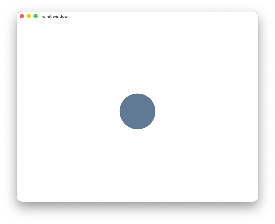
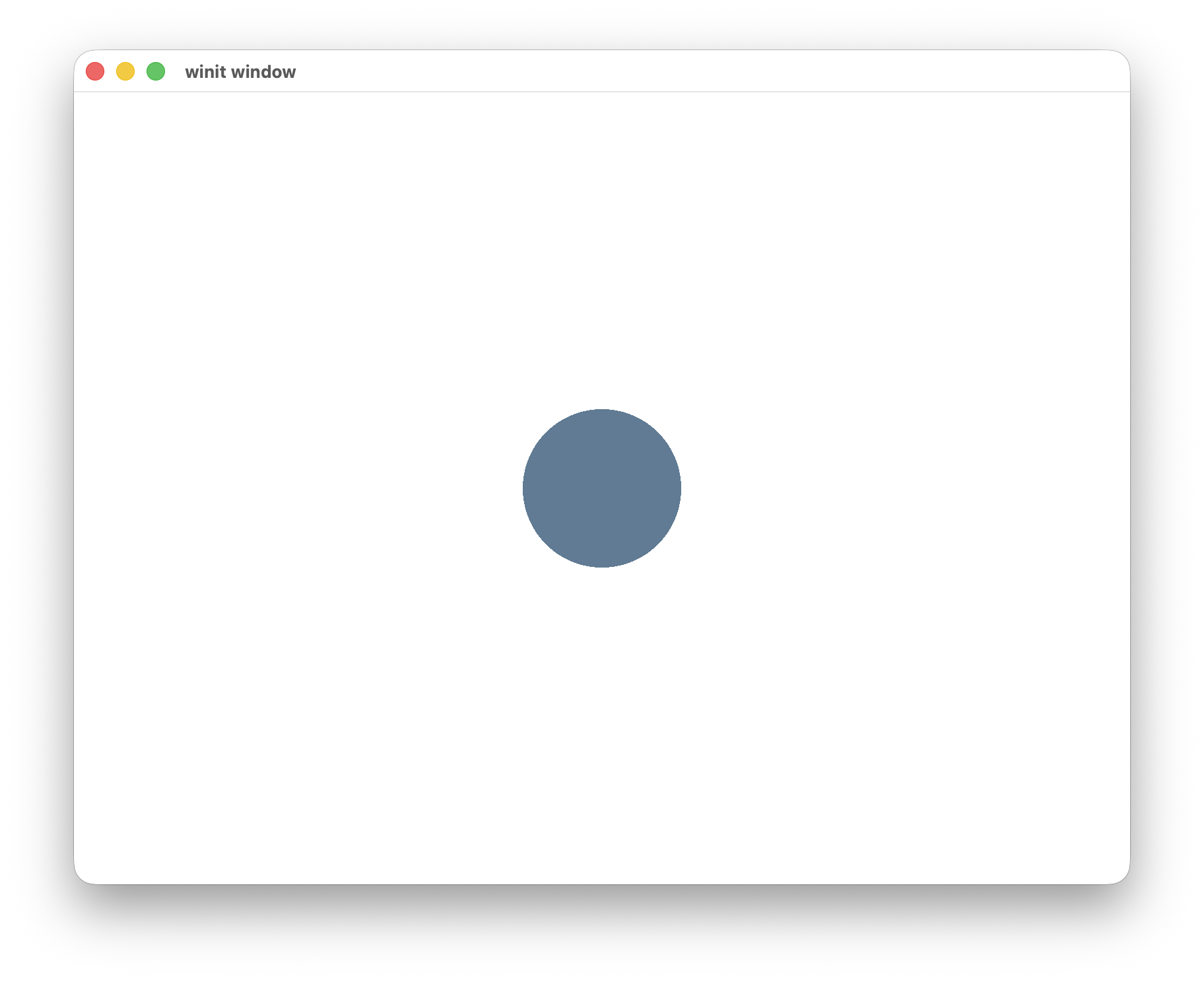
In this post, you will learn how something like the following is made using the GPU.
The code snippets I will be using are in Rust with WGPU but most of the post is language and API agnostic.
Prerequisites#
Things I'm not going to cover in this post (to keep the post short):
- How to set up
WGPU, there's a great guide that does this much better than I can. - Details of the whole graphics pipeline and how GPUs work. To learn more, see learn-wgpu, learnopengl and in the renderhell-book
Things I will cover:
- Fundamentals on drawing rectangular and circular shapes with the GPU.
- How to dynamically modify their size.
Graphics Programming Terminology#
While this isn't a tutorial on graphics programming in general, we need to cover some terminology we will be using.
- Shader: A shader is a program written by the application developer and is sent to the GPU for execution.
There are many types of shaders, but in this post we will use the Vertex and Fragment shaders.
- Vertex shader: The vertex shader takes each vertex (which is a point in 3D space) and converts it in the way we want, e.g. move it by some offset.
- Fragment shader: In the fragment shader we can define the color of each pixel (this is a simplification, we can have more fragments than pixels).
- Uniform: Uniforms are shader variables that remain constant across all vertices and fragments in a single draw call. They are stored in uniform buffers.
Note: The shaders you will see in this post are written in a language called WGSL (WebGPU Shading Language).
Note: I've created a repo that recreates every shape in this post. At the end of each section, there will be a link to a commit you can use to reproduce the shapes.
Drawing a rectangle#
Let's start with the simplest shape we can draw, a rectangle.
Describing the rectangle#
A vertex shader is executed on every vertex we have passed to the GPU. When defining a vertex we can add input data which will make it easier to perform different actions on each one.
So if we want to place a shape in a specific location on the window we need to specify the location of each vertex.
struct VertexInput {
    @location(0) position: vec2<f32>,
}
Describing a rectangle requires only 4 vertices, and this is how they look in clip coordinates.
When we pass vertices to the GPU, we need to tell it how to connect them.
WGPU supports different topologies
PointList: Each vertex is a point.LineList: Four vertices form two distinct lines.LineStrip: Four vertices form one continuous line.TriangleList: Six vertices form two distinct triangles.TriangleStrip: Six vertices form one continuous triangle.
A rectangle can be split into two triangles.
So we can use a TriangleList topology and submit 6 vertices which will form two distinct triangles. Of course, we reuse
vertices because we only need 4 unique positions.
let x2 = x + side;
let y2 = y - side;
let vertices = vec![
    Vertex { position: [x, y] },
    Vertex { position: [x, y2] },
    Vertex { position: [x2, y2] },
    Vertex { position: [x2, y] },
];
let indices: Vec<u16> = vec![0, 1, 2, 0, 2, 3];
We need a way to pass the vertex and index data to the GPU. This is done using the vertex and index buffers.
Shader#
Now that we've described our shape, it's time for drawing it.
// The input to our vertex shader is a 2D position.
struct VertexInput {
    @location(0) position: vec2<f32>,
}

// The output of our vertex shader is a 4D position.
struct VertexOutput {
    @builtin(position) clip_position: vec4<f32>,
}

@vertex
fn vs_main(in: VertexInput) -> VertexOutput {
    var out: VertexOutput;
    out.clip_position = vec4<f32>(in.position, 0.0, 1.0);
    return out;
}

@fragment
fn fs_main(in: VertexOutput) -> @location(0) vec4<f32> {
    return vec4<f32>(0.1, 0.2, 0.3, 1.0);
}
- The vertex shader writes the clip space position.
- The fragment shader outputs a constant color.
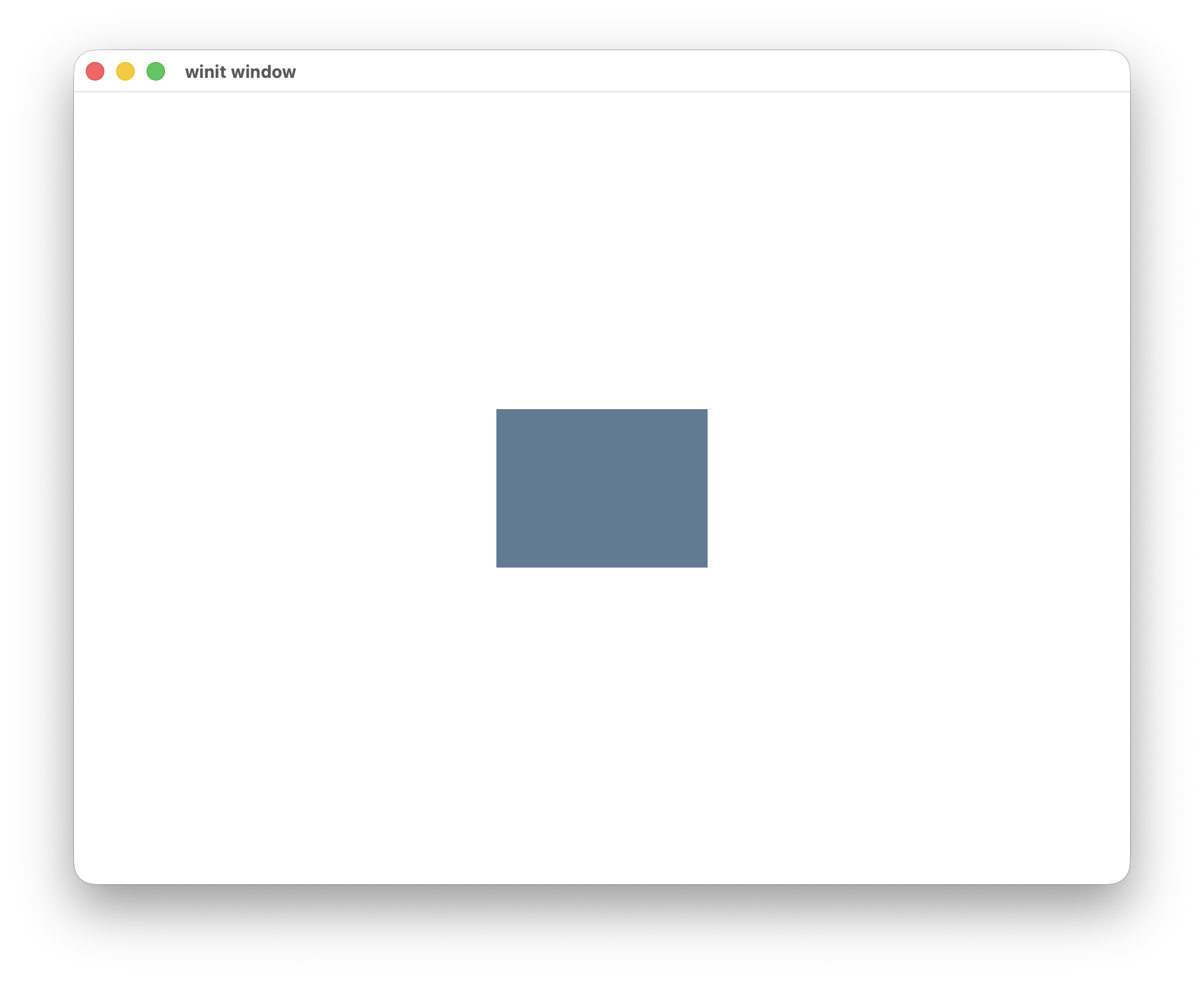
This is all we need to draw a rectangle. Running this shader will show an unimpressive rectangle.
Drawing a circle#
The next step is to learn how to draw a circle.
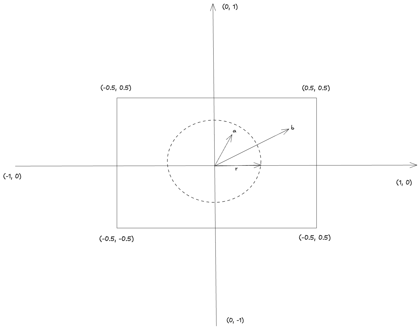
The simplest way to go from a rectangle to a circle is to define a radius r and to discard any fragments
whose distance from the center exceeds the radius.
We want every pixel with a distance from the center smaller than r to be drawn, the rest should be discarded. This is also very well explained in
the book of shaders (see Circles).
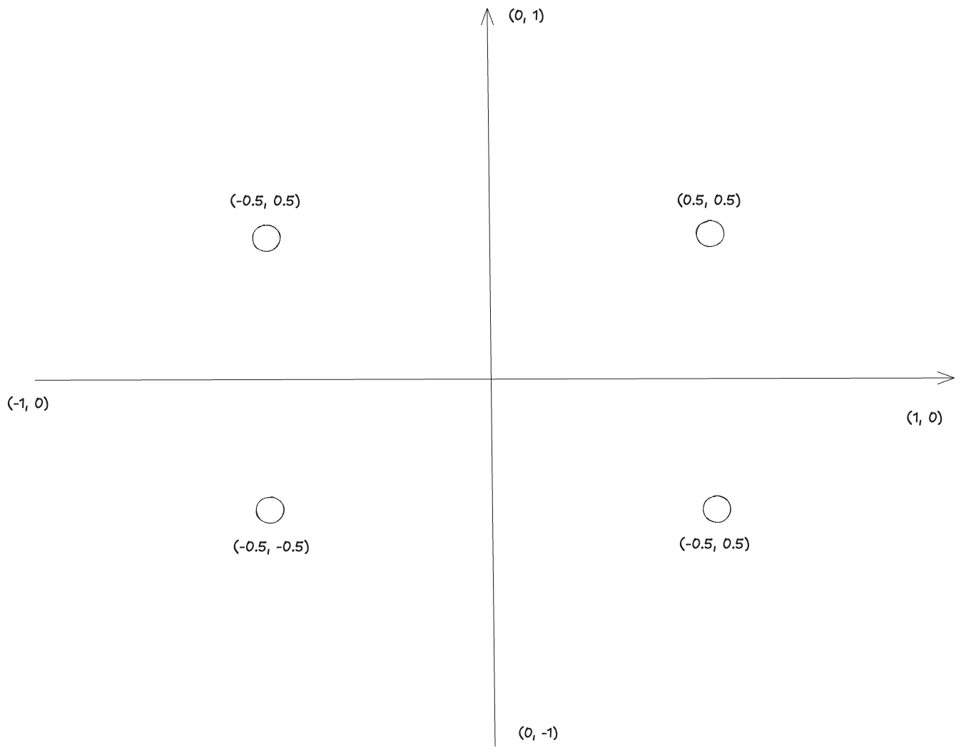
In order to calculate each pixel's distance from the center we need to make some changes to our shader. We are going to
add normalized coordinates to our vertex input. The normalized coordinates will always be between [-1, 1] in
both dimensions and the center of our shape in (0, 0).
We will rely on the GPU's interpolation for this.
While the vertex shader runs on the vertices we have defined (6 times in our example), the fragment shader runs for every pixel.
So how do we get input values for every pixel while we have only created 6 vertices?
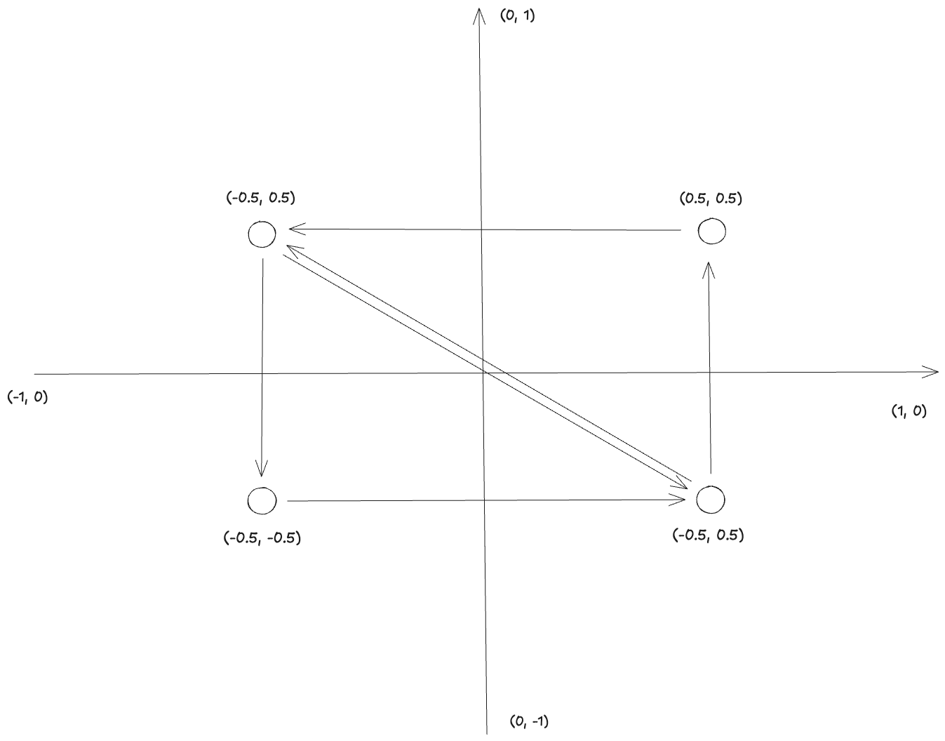
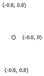
The answer is, that for every pixel the fragment shader reads the input values of each vertex in the primitive (triangle in our case) and then interpolates the current value based on its position.
For example, a point interpolated between (-0.5, 0.5) and (-0.5, -0.5) has coordinates (-0.5, 0.0).
This is how our updated vertex input/output and vertices look.
struct VertexInput {
    @location(0) position: vec2<f32>,
    @location(1) uv: vec2<f32>,
}

struct VertexOutput {
    @builtin(position) clip_position: vec4<f32>,
    @location(1) uv: vec2<f32>,
}
let vertices = vec![
    Vertex { position: [x, y], uv: [-1.0, 1.0] },    // top-left
    Vertex { position: [x, y2], uv: [-1.0, -1.0] },  // bottom-left
    Vertex { position: [x2, y2], uv: [1.0, -1.0] },  // bottom-right
    Vertex { position: [x2, y], uv: [1.0, 1.0] },    // top-right
];
Now making our rectangle a circle should be just a matter of changing our shader to this.
@vertex
fn vs_main(in: VertexInput) -> VertexOutput {
    var out: VertexOutput;
    out.clip_position = vec4<f32>(in.position, 0.0, 1.0);
    out.uv = in.uv;
    return out;
}

@fragment
fn fs_main(in: VertexOutput) -> @location(0) vec4<f32> {
    var alpha = 1.0;
    let dist = length(in.uv);
    if (dist > 0.8) {
        alpha = 0.0;
    }
    return vec4<f32>(0.1, 0.2, 0.3, alpha);
}
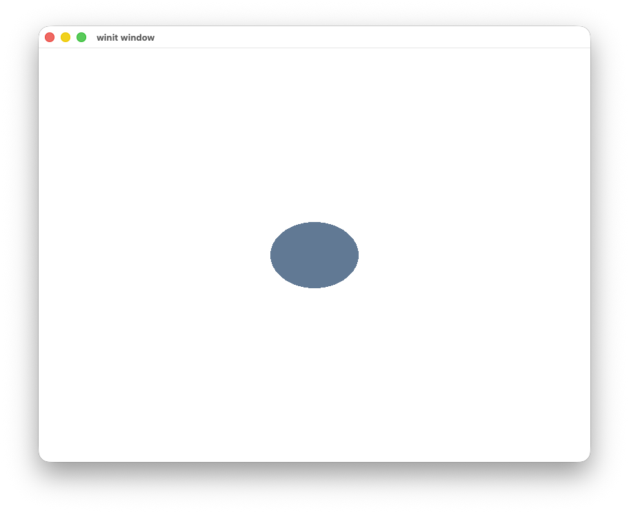
And the result is not what we wanted.
Instead of a circle, we got an ellipse with some aliasing on the edges.
From an ellipse to a circle#
You might be wondering why our shape is an ellipse and not a circle.
This is because our initial shape is a rectangle and not a square, despite using the same length for width and height. The length is proportional to the window dimensions, so a length of 1 in each dimension is
- 0.5 of the window width
- 0.5 of the window height
If we want to make our rectangle a square, we need to use different lengths for the width and the height. For example if the
window_width is 2 * window_height and our rectangle height is a then the rectangle width needs to be 2 * a to have a square.
Because the window dimensions could change dynamically, instead of recreating our vertices we can make this transformation in our fragment shader.
We will pass the window dimensions to our shaders using a uniform buffer.
struct QuadUniforms {
    window_size: vec2<f32>,
}

@group(0) @binding(0)
var<uniform> quad_uniforms: QuadUniforms;

@fragment
fn fs_main(in: VertexOutput) -> @location(0) vec4<f32> {
    var alpha = 1.0;
    let aspect_ratio = quad_uniforms.window_size.x / quad_uniforms.window_size.y;
    let corrected_uv = vec2<f32>(in.uv.x * aspect_ratio, in.uv.y);
    let dist = length(corrected_uv);
    if (dist > 0.8) {
        alpha = 0.0;
    }
    return vec4<f32>(0.1, 0.2, 0.3, alpha);
}
In let corrected_uv = vec2<f32>(in.uv.x * aspect_ratio, in.uv.y) we multiply the X coordinate with the aspect ratio
because we want to compensate for the wider viewport.
With these changes we should get a circle now.
Remove aliasing#
We get aliasing to our circle, because we abruptly switch from visible to invisible pixels, which creates jagged edges.
We can fix this using the smoothstep function. smoothstep(a, b, x) performs interpolation from 0 to 1 between two values a and b, where a < b.
Given a value x, the result y is:
1whenx > b0whenx < a- in
[0, 1]whena < x < b
You can read more details in thebookofshaders.
So if we want our radius to be 0.8, we can do something like
@fragment
fn fs_main(in: VertexOutput) -> @location(0) vec4<f32> {
    let aspect_ratio = quad_uniforms.window_size.x / quad_uniforms.window_size.y;
    let corrected_uv = vec2<f32>(in.uv.x * aspect_ratio, in.uv.y);
    let dist = length(corrected_uv);

    let alpha = 1.0 - smoothstep(0.78, 0.8, dist);

    return vec4<f32>(0.1, 0.2, 0.3, alpha);
}
We set alpha to 1.0 - smoothstep, because smoothstep is 0 below 0.78, 1 above 0.8
and increasing between them.
Let's see how the smoothing width affects our circle. Below we have used 0, 0.1 and 0.5, with a radius of 0.8:
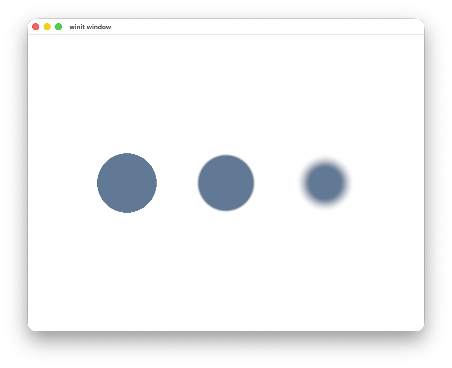
- 0 gives us jagged edges (as expected)
- 0.1 gives us blurry edges
- 0.5 gives us a blurry circle
Which is expected, the bigger the difference between a and b the more area will be interpolated.
A value of 0.02 gives us a nice circle.
Instead of picking an arbitrary number for the edge we can use fwidth(dist), which approximates the width of a pixel footprint.
Running our shader now will produce a circle.
Drawing a ring#
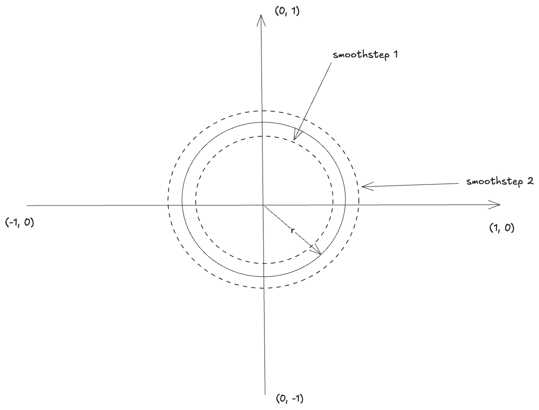
Now that we know how to properly draw circles, we can move to a ring right? We just need to do two smoothsteps,
one for the outer circle, one for the inner and take their intersection.
@fragment
fn fs_main(in: VertexOutput) -> @location(0) vec4<f32> {
    let aspect_ratio = quad_uniforms.window_size.x / quad_uniforms.window_size.y;
    let corrected_uv = vec2<f32>(in.uv.x * aspect_ratio, in.uv.y);
    let dist = length(corrected_uv);

    let radius = 0.8;
    let ring_half_width = 0.1;
    let edge = fwidth(dist);
    let outer = smoothstep(radius - ring_half_width - edge, radius - ring_half_width + edge, dist);
    let inner = 1.0 - smoothstep(radius + ring_half_width - edge, radius + ring_half_width + edge, dist);
    let alpha = inner * outer;

    return vec4<f32>(0.1, 0.2, 0.3, alpha);
}
There is a small problem with our approach. If ring_half_width is smaller than edge, then the two smoothstep functions will overlap,
the opacity will start decreasing and our ring will start fading.
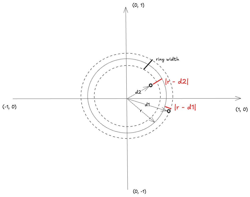
One solution is
let radius = 0.8;
let ring_width = 0.02;
let edge = fwidth(dist);
let ring_dist = abs(dist - radius);
let alpha = 1.0 - smoothstep(ring_width * 0.5, ring_width * 0.5 + edge, ring_dist);
Why this works:
|r - d|is the distance to the rings edge.- Outside the ring we have
|r - d2| > half_ring_width, therefore alpha will be 0. - Inside the ring we have
|r - d1| < half_ring_width, therefore alpha will be 1.
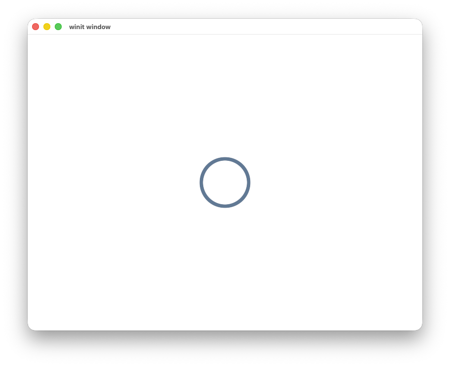
And now we can draw rings.
Running our shader now will produce a ring.
Make them breath#
Now that we have the building blocks we can make our shapes to breath.
We need to make the radius configurable for this, so we will extend our uniform buffer
struct QuadUniforms {
    window_size: vec2<f32>,
    radius: f32,
}
We can now change it from our CPU program after rendering a frame.
render_pass.set_vertex_buffer(0, quad.vertex_buffer().slice(..));
render_pass
    .set_index_buffer(quad.index_buffer().slice(..), wgpu::IndexFormat::Uint16);
render_pass.draw_indexed(0..quad.index_count(), 0, 0..1);
quad.update_radius(&self.queue, &self.uniform_buffer); // new

//...
pub fn update_radius(&mut self, queue: &wgpu::Queue, uniform_buffer: &wgpu::Buffer) {
  // Slowly reduce the radius
  self.radius -= 0.01;

  // Clamp to avoid negative values
  if self.radius < 0.0 {
      self.radius = 0.0;
  }

  // Update the uniform buffer (only the radius at offset 8 bytes)
  queue.write_buffer(uniform_buffer, 8, bytemuck::cast_slice(&[self.radius]));
}
Our implementation doesn't do anything useful for now other than making our circle slowly disappear.
Let's make it breath by calculating how much the radius should change per millisecond in order to fill the whole radius in a given duration. We will also store a min and max radius to stop the shape from going to zero.
let radius = max_radius - min_radius;
let step_per_millis = radius / animation_duration.as_millis() as f32;

pub fn update_radius(&mut self, queue: &wgpu::Queue, uniform_buffer: &wgpu::Buffer) {
    if self.start_time.is_none() {
        self.start_time = Some(std::time::Instant::now());
    }
    let elapsed = self.start_time.unwrap().elapsed();
    let step = elapsed.as_millis() as f32 * self.step_per_millis;

    let radius = match self.direction {
        Direction::Up => {
            let radius = self.min_radius + step;
            if radius > self.max_radius {
                self.direction = Direction::Down;
                self.start_time = None;
            }
            radius
        }
        Direction::Down => {
            let radius = self.max_radius - step;
            if radius < self.min_radius {
                self.direction = Direction::Up;
                self.start_time = None;
            }
            radius
        }
    };
    queue.write_buffer(
        uniform_buffer,
        8,
        bytemuck::cast_slice(&[radius]),
    );
}
Here we do the following:
- We store a direction for our shape on creation.
- If the direction is up, we increase the radius based on the elapsed time. If it's down, we decrease it.
- When we reach the upper or lower radius limit we flip the direction and reset the time.
Summary and next steps#
In this post we covered:
- How to draw circular shapes.
- How to correct a non-square viewport.
- How to get smooth edges with
smoothstep. - How to animate a "breathing" radius over time.
At Hopp, our pair programming app we used a combination of these animations to show where a remote participant is clicking on the sharer's screen.

If you have any questions or suggestions for future posts feel free to reach out at X/twitter or email me directly at iason at gethopp dot app.
PS: I recently decided that I want content written by me to be authentic, so no AI was used for writing this post.